Matt Jones Tech
  • Blog
  • Video Projects
  • Web Projects
  • Designing and Printing A Tail Tidy for a 2022 Honda Grom

    Designing and Printing A Tail Tidy for a 2022 Honda Grom

    Step 1: What’s out there already?

    During my initial research, I found that there were a few models already out on thingiverse, which gave me a good place to start. At least I could use the measurements and dimensions of the license plate mount! And just to begin, I was only able to speculate if the parts out there would fit my ’22 Grom, even though the parts I found were designed for a ’18.

    From what I understand, there was a pretty good amount of bodywork that was updated for the ’22 Grom, so I would definitely be surprised if the part designed for a ’18 would fit, but I figured I’d give it a shot.

    Not surprisingly, the part didn’t fit, but it was a great starting point because at least I had something I could mount the tag to, as well as a pre-designed fitting for the stock tag light housing.

    Step 2: See What I’m Working With

    The part of the part (engineering is difficult to explain!) that holds the tag was great and was perfectly fitting to reuse in the first iteration of my redesign. From ’18 to ’22, the undertail had been pretty well redesigned, meaning the ’22’s undertail was much narrower and a completely different shape. The ’22 has a sort of trapezoid shape that is inset for the tail with asymmetrical holes for bolts and wires. With that in mind, and a caliper in my hand, I got to work jotting down all the measurements.

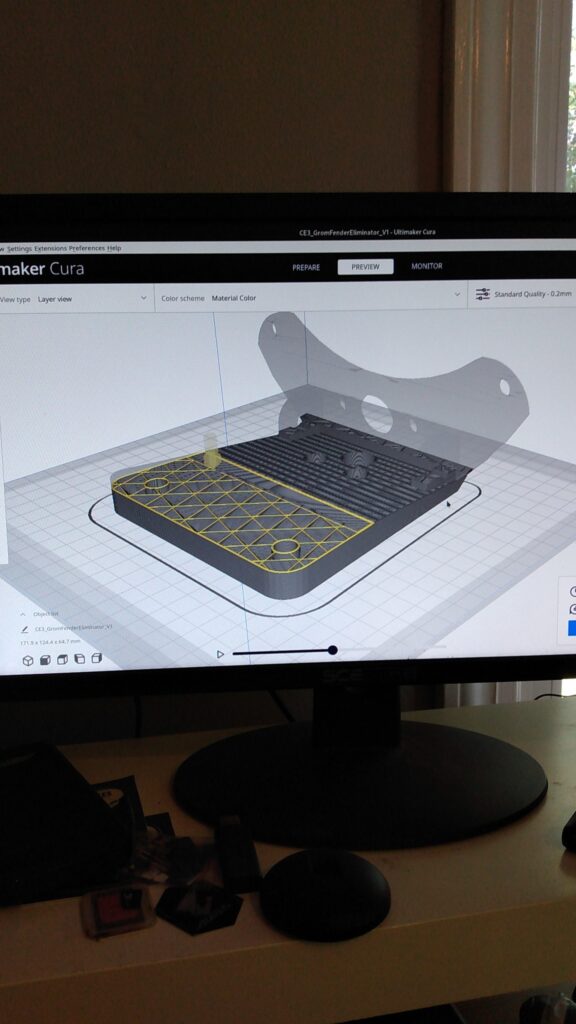
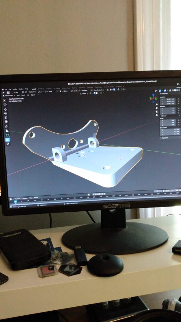
    Step 3: Crack Open A Can of Blender

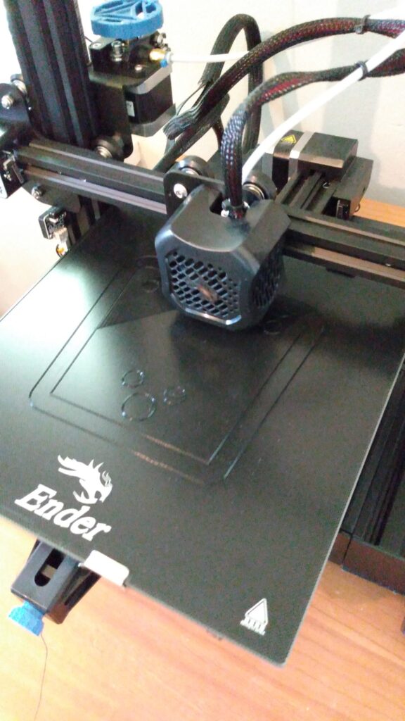
    With measurements in hand, I went ahead and began working on the design. I was able to import the .STL file from Thingiverse which gave me a good starting point. The only strange thing with .STL file imports from online is the scaling isn’t always preserved. For some reason, the .STL was something like 10,000 times larger than Blender scale. For 3D prints, I typically use millimeters as the default unit of measurement since my print volume is 220mm*220mm*250mm. Luckily I was able to fix the scale by changing it from 1 to something like 0.0001 (again, not sure on the number of zeros, but I got it eventually).

    Using my measurements from the garage, I was able to create the shape of the volume to fill the inset of the undertail. Once I’d modeled everything to scale, I scaled everything down just a “smidge” to ensure that the piece would fit. After all, making a peg with the same dimensions as the hole would ensure that the peg won’t fit in the hole. So there’s a little bit of “feeling” that goes into the calculations.

    Step 4: Discover Your Oversights

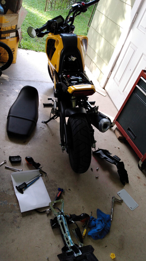
    This one was tough because it really required me to be intentional about making absolutely sure that the turn signals had enough room to be mounted flushly against the side of the tail tidy, while at the same time, not interfering with the overall design in such a way that would prevent the entire part as a whole from not fitting within the undertail inset. Again, kinda difficult to explain, but once you’re this far in it, I just kept feeling my way through it until I got it right. Luckily I had some filament I didn’t mind using to create these early prototypes. That way I can just print my next iteration and discover its flaws as I try to install it.

    Step 5: Redesign, Reprint, And Discover Your Other Oversights

    In my second design, I knew I had to bring the turn signal mounting holes up forward, so they weren’t up against the tag mount. In doing so, I also took the liberty of making some holes to route wiring that made more sense and aligned with existing holes in the underseat bodywork. With those changes made, I cleaned off the print bed, re-leveled the bed, and sent the print off to run overnight. This one was much closer, and the part fit more suggly in the undertail inset. This time, because the turn signal mounts weren’t flush with the edge of the part, mounting the signal was impossible. Also, the mounting point was so high against the undertail, even if it was flush, the signal would not be able to clear the bodywork to achieve a flush mount.

    Step 6: Redesign, Reprint, and Barely Get Away With It

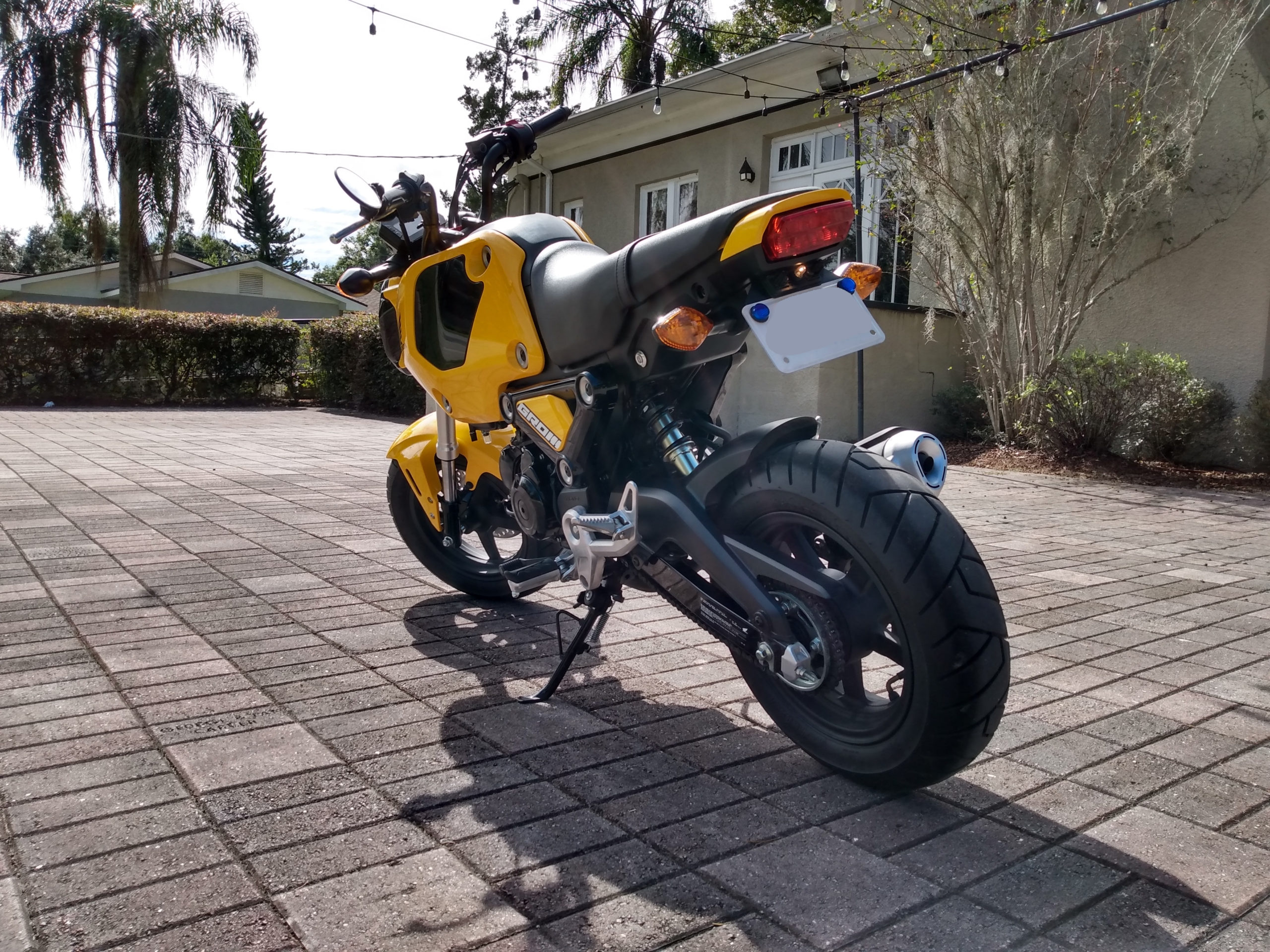
    With the turn signal mounts finally low enough and flush enough to mount actual turn signals, the rest of the design worked pretty well. It took some finagling, but I was finally able to run the wiring that previously existed in the huge stock fender back up underneath the seat. A last minute change in version 3 was the decision to increase the angle of the tag mount so that the tag faced more upward instead of being so flat as you can see in the next to this paragraph. Unfortunately, that decision ate into the space I needed to mount the stock tag light housing (which turned out to be required, due to the sizing and spacing of the holes above the plate. They were designed to mount the stock tag light housing).

    However, I was able to use a part of the stock tag light housing to mount the light and get it working. For the time being, I’m totally fine riding with a bare bulb for the tag light. If I were to do a version 4, I’d probably make a version that can accommodate the entire stock tag light housing, as well as an alternate version that would have a custom tag light housing built in. If you guys are interested in me doing that and making it available, just let me know and I’d be happy to design and print it for you for $25 plus shipping.

    Step 7: Shred The Streets

    That’s it for this design and build, thanks for checking it out! If you’d like me to design and build any other cool Grom accessories, I have a ’22 Grom now, I freaking love it, and I’m probably going to print more stuff for it. Ride safe and praise God always.

    matt

    November 7, 2021
    3D Modeling, 3D Printing
  • Designing and 3D Printing From Scratch

    The First World Problem

    When I first got my 3D printer a few weeks ago, my mind was racing and coming up with all sorts of crazy stuff to print. I still constantly think, “Can I print that?”. Learning about the limitations of what a printer can and can’t do is definitely interesting and presents a sort of fun challenge. After burning through all my sample filament after initial setup on my first weekend of printing, I wanted to make my first roll of “real” filament count. So instead of just printing a bunch of files I found online (most of which disappeared under the piles of toys in my kids’ room) I wanted to print something that would actually server a purpose and be useful instead of a Flexi Rex. No offence to Flexi Rex- He’s definitely a cool way to learn about 3D printed hinges!

    I recently got a new toothbrush and it didn’t fit in the built-in holder in the bathroom. Yes, first world problems, I know, but just for the sake of creating something that was a “custom” design to solve a problem and be useful, I thought this was a good starter candidate. Hopefully I’ll get better at solving issues with better, smarter 3D prints down the road, but this will be a fun learning experience!

    Some measurements had to be estimated just because I couldn’t exactly wrap the caliper around certain parts of the brush and the entire caliper wasn’t capable of measuring the entire length of the brush. So as a rough estimeate, I held the caliper beside certain design elements of the brush just to get that individual part’s size. I measured the handle and the brush head separately. I think this worked out better anyway, simply because the handle is a lot bigger in diameter than the brush head anyway, plus the tapering of the handle into the shaft of the brush head was a design feature that I wanted to take note of, especially since I was designing the toothbrush holder to be compatible with this specific model brush.

    Step 1: Measure Everything

    The first step was to get as many measurements of my toothbrush as I thought would be needed. I measured the base, the handle, and brush heads in both directions which essentially produced a box model that represented a bounding box for my toothbrush. With those dimensions in place, it was time to start my simple toothbrush holder design.

    Speaking of being compatible with this specific model of toothbrush, I wanted to design a wall-mounted toothbrush holder that could accommodate two brushes, as well as allow both of those brushes to be charged simultaneously as they were being stored. My original design was a small, miniature table-like design that would have sat on the countertop beside the sink. However, after rethinking the idea, there’s not a ton of countertop space to spare, so I switched gears and started thinking about a wall-mounted design that achieved essentially the same functionality as the original plan. Just hang two brushes and allow them to charge while hanging.

    Step 2: Creating a Rough Scale Model

    Once I had collected all of the measurements of my toothbrush, it was time to crack open Blender and enter in all my measurements. Once I created some basic bounding boxes for my toothbrush measurements, it almost, sorta, kinda began to look like a toothbrush.

    Once I had the toothbrush modeled, I was ready to begin work on the design of the toothbrush holder. Just to illustrate my first idea, it was going to be a sort of table-top design with two large holes for the handles that stepped down into two samller holes that extended through the bottom of the frame. The smaller holes would allow for toothbrush charging while resting on the platform. The platform would be supported by 4 legs at the corners. As I mentioned before, this design was okay, but meant crowding up an already limited countertop.

    Step 3: Modeling the Holder

    Once I had the toothbrush reference model in the scene, I was ready to begin designing a simple wall-mounted holder. Since there are a zillion toothbrush holder out there already, it wasn’t hard to settle on a simple, tried-and-true hanging design. The holder would consist of a main panel with small hooks protruding from it that would cradle the brush head.

    Step 4: Exporting For Cura

    This was the sleeper challenge on this project. For some reason I hit a wall going from Blender to Cura for printer export. Even though I had modeled everything to scale in millimeters in Blender, for some reason, I kept getting issues when attempting to import into Cura, my slicing program. Long story short, and after several several several failed export attempts, I think I can fairly safely conclude that most of the issues were caused by not running the model through the 3D Print Toolbox addon. During the modeling process, I employed a stack of modifiers to get the design I was looking for. Even after applying scale, rotation, location, I was still getting import problems from Cura saying the model was extremely small and had to be scaled up 10,000 times, and it still wasn’t visible. Finally, I realized I wasn’t running the 3D Print Toolbox addon, so I gave it a shot. To my surprise, I found faces that were inside the mesh that weren’t supposed to be there (as a result of a mirror modifier). After cleaning up over 400 duplicated vertices, I re-imported. It came in, but the scale was still messed up. I ended up scaling 1000% in Cura and double checked the dimensions to ensure they were the exact same as the dimensions coming from Blender. The seemed to match, so I went ahead and sliced the model.

    Once the print came off the bed, it was time to see if the brush actually fit. It did… kinda. Turns out I was a bit TOO precise with the exact width of the brush neck and ended up modeling too close to my reference. It kinda fit, with the bristles facing outward, but it fits much more confortably with the bristles facing right or left. Just not to self, leave room for error, leave room for breathing, leave room for ease of putting the brush in the slot imperfectly. Other than that, it works!

    matt

    May 10, 2021
    3D Modeling, 3D Printing
  • Learning How to 3D Print

    The Research

    Last weekend, I started doing research on 3D printers. It’s crazy to think that 3D printing has already been around for 10+ years! So, like with anything in the tech world, the longer it’s available, the better the technology gets and the lower the price gets. Who knew that you can get your very own entry-level desktop 3D printer for around $300? So I started researching all the different types of 3D printing, different methods of printing, different types of filament, the different physical characteristics of filament, etc. I’ll spare you all the details, but I ended up settling on a printer that was released in 2020 (last year, at the time of this writing). So it was relatively new, and the price point was just what I was after. There were lots of benefits to this printer and having a large community, software availability for Linux, and a sub $500 price tag were my top 3 criteria.

    The Build

    There will likely be people out there who would chalk this one up as a negative thing for the Creality Ender 3 V2, but I personally didn’t mind. There was a decent amount of setup before you could do your first print. Now, keep in mind, I’m brand new to 3D printing, and I had almost no idea what to expect. Some printers like MakerBot and some others are ready to print right out of the box. However, because there is so much assembly on the front end, I think it helped me gain a better understanding of what everything does, where everything goes, and how it all works together. That way if (when) anything breaks or wears out, I’ll know what it is and how to replace it. So first up, get everything out of the box.

    Just beneath the top layer of foam was the first layer of printer components.

    The Instructions

    It’s all too easy to criticize some instruction manuals, but this manual, I think was fair. It got me most of the way there. The only thing I had to go beyond the manual to figure out how to do was bed leveling, because the way I was doing it was going to take me legitimately 2 hours. The pictures were pretty clear, but you did have to pay very close attention to them! Some of the parts were EXACTLY the same, with the only difference being where holes were drilled. I did have a couple of times where I put a part on, then realized I had to take it right back off because there was physically no way to assemble the next part with the previous part still on.

    These are all the parts (mostly) flat on a table. Soldering iron is not included or required for assembly. It just happened to be on my desk.

    Note: The soldering iron was not included or required for this assembly. It just happened to be sitting on my desk.

    Step 1

    Install the Z-axis profile (left). This was pretty straighforward. The only thing that was a little tricky was the Z-axis limit switch. Once you figure out the method used to attach it, the same method is used to attach other components the same way.

    The Z-axis limit switch was particularly trick to get installed. Once you know the method used to attach, the rest of the components use the same method.

    Step 2

    Once the left Z-axis profile is up and the Z-axis limiter switch is installed, you’ll want to install the right Z-axis profile. In the manual, all this happens in one step.

    Step 3

    In the photo above, you can actually see the Z-axis motor kit and T-type screw have already been assembled and installed. The T-type screw came with a protective rubber sleeve. You’ll want to remove that before installing.

    Step 4

    Install pneumatic joint, XE-axis kit, and synchronous belt. Sounds complicated, but it’s not that bad. I did have to run a search for the pneumatic joint, just because I was unfamiliar with what it looked like and how big it was. Once I saw a photograph, and not a drawing, it was easy to find. 2 pneumatic joints are included with the printer and they’re both in a small pouch with some other parts. So if you’re not exactly sure what you’re looking for, it can feel like it might be missing or something. Once the XE-axis kit is assembled, you roll on the nozzle kit from the END. At first glance, I was under the impression I’d have to remove one of the wheels on the nozzle kit to have it hook over the edge of the XE-axis it. Great news, you don’t have to go through all the trouble. Simply slide the wheels over the end of the gantry bar. By the time you’re done, you’ll have something like the pics below.

    Gantry installed.

    Step 5

    Install the X-axis tensioner. This one, for me, was pretty confusing. The way the illustrations were drawn made it seem like I was missing a pulley wheel that went on the right end of the X-axis profile. Turns out, by the time I’d finished this step, the artist just drew the X-axis tensioner belt unnaturally curving around an invisible part that wasn’t addressed. Once I put that together in my head, the rest was easy. I kinda group a few of these steps together and skipped ahead just to see if the next steps would give me clues on how to complete my current step. That method seemed to work for me.

    Steps 6-9

    By this point, your build should be really starting to look like the picture on the box. The only steps that really remain are applying the gantry, which just screws into the top of both Z-axis profiles, install the material rack, and plug in each of the components. Once you follow the wires and look at each of the connections, it’s pretty easy to hook up. Each of the connections are pretty dummy proof. Once you install the screen on the right side of the base, you’re almost ready to print!

    First Boot Up

    My First Mistake

    It was bound to happen, so I guess it was best to go ahead and get it out of the way before I even printed anything. I’d assembled everyhing and just turned on the printer. it was idle, just sitting at the start up screen. Awesome, no problems. Next came the step where I needed to level the print bed. There are wheels under each of the corners of the print bed that adjust the hight of the bed to make sure it is level. Right out of the box, who knows what level they’re at. Unfortunately, there’s no real warning in the manual, so I figured out how to ACTUALLY level the bed after I’d layed a huge scratch into the bottom edge of my print bed. I hit “auto-home” which sent the nozzle to the bottom left corner of the print bed. I adjusted that corner, then with servo motors engaged, told the nozzle to move to the other corner of the bed. It started scraping its way to the other corner and there was nothing I could do. The motors started grinding and popping and then it hit the clip on the bottom edge that holds the glass in place. It was so awful, but now at least I know to ALWAYS level the be with servo motors DISENGAGED.

    Get On With It Already! Let’s Print!

    The SD card that comes included with the printer has two default “test” files that are already on it. They come in the form of .gcode files. .gcode is essentially the result of slicing software, but it’s path instructions for the nozzle. Where should it go and when it should start and stop the flow of print filament.

    First Print

    The two test files included with the Ender 3 V2

    matt

    May 4, 2021
    3D Modeling, 3D Printing
  • The Museum: Update #2

    Progress update for my new web developer portfolio. Creating a 3D museum to showcase all my stuff from 10 years of film and video production. Final product will be a static HTML website that features a full screen 3D museum environment that the user can walk through and interact with.

    If you missed the first update and initial explanation, checkout the first one!

    Creating a Web Developer Portfolio

    As a new web developer, I’m looking for a unique way to showcase all of my skills that I’ve acquired over my 10 year career in visual media. I hope you guys like it!

    matt

    April 21, 2020
    3D Modeling, Graphic Design, Web Development
    3d modeling, b3d, Blender, web design, web development
  • The Museum: Update 1

    The first update of who knows how many… Super excited to start a new project!

    matt

    April 15, 2020
    3D Animation, 3D Modeling, Blender, Web Design, Web Development
    3d modeling, b3d, Blender, portfolio, vlog
  • 3D Cursor In Blender

    Using the 3D Cursor in Blender

    Intro

    Hey guys, what’s going on! In this video, we’re going to take a look at how to use the 3D cursor in Blender. The 3D cursor is, if you take everything and delete it, it is this little circle here in the center. That is the red and white circle; the little crosshair thing. In 2.8 and above, they have added a special 3D cursor tool to allow you to move and drag the cursor around. If you’re familiar with any kind of word processor or typing code, it’s very much the same idea. A cursor is just a thing that helps you know where you’re working.

    First Example

    For example, if I hit SHIFT+A on the keyboard that will bring up the “Add” menu. Let’s just say I want to add a cone. This will add a cone to the scene, but it will add it exactly where I’ve put my 3D cursor. So for example, I can take the cursor tool, move the cursor way over here, and add a monkey head. That monkey head will appear here, exactly where I’ve put the cursor. So that’s cool, to have it put stuff exactly where I want it to appear. Especially if you have a massive scene and you’re adding stuff all over the place. If I want to add something way out here I can do so without having to go all the way up and get something that appeared somewhere that I didn’t need it to appear.

    Another Example

    Another great use for the 3D cursor in Blender- you can hit SHIFT+S to bring up the snapping menu popup; and this is especially useful if you’re going to do some editing. So for example, if we bring up the monkey Suzanne here for a second, and I hit TAB on the keyboard to enter edit mode. Let’s just say I want to create something in the center of Suzanne’s eyeball. I’m going to hit X on the keyboard and delete the center vertex on the eyeball. So that is going to open up a hole in the eyeball. Next, I’m going to hold ALT on the keyboard and click this edge and that’s going to select all of the vertices inside of this eye socket area. And so what I can do is go back to the SHIFT+S menu to bring up the snapping popup. Then I can choose to snap the cursor to what I have selected. So the cursor will appear exactly in the center of the eye. So then I can go and add a cone or something that will be specifically in the center of the eye.

    The pivot point menu

    Actually, that was not a great example because I have ‘active element’ currently selected. So this menu up here is the pivot point for transforms. I’m going to choose 3D cursor and then let’s see the difference that that’s going to make. So I’m going to go ahead and add a cone and it’s going to scale it now, this time, scaling from the 3D cursor. It’s a great reference point to be able to pivot scales and rotations around an element or a point that’s not a vertex. So if I go to- this is what I had it on previously- the active element, so here, you can see I’ve selected all the vertices on the bottom of this cone; whichever one (I’m shift-clicking) is white is the active selection, so it will scale from that point. So anyway, the cursor is always available if you’re trying to scale something, rotate something, or create a pivot point, or define or create a center on something, the 3D cursor is a great way to do that.

    The Door Example

    Okay, here’s a good example use case for the 3D cursor: Let’s say for example, I want to model a door. I might start with a plane and I might rotate it on the X axis for a little bit and scale it along the X. And this is just a rough, general idea for the shape of my door. But when I rotate it like this, it doesn’t rotate quite like I want it to. So an important concept for animations especially, is the idea of knowing where your pivot point is. Usually on all objects that are added through the context menu have the default pivot point (or ‘origin’ as it’s known in Blender) located in the center of mass. Of course, if you model a lot of new geometry onto a base shape, the origin will remain exactly where it was in object mode, even if you completely change the location of the whole shape.

    So back to the door example, I want my door to rotate from the edge, like a normal door. So what I can do is go into edit mode, and have edge selection mode enabled, and select the left edge. Then hit SHIFT+S to bring up the snapping menu, and choose Cursor to Selected. That’s going to bring the cursor to the center of these two vertices, basically the center of this left edge. Then hit TAB to go back into object mode, and in the pill menu at the top, choose Object > Set Origin > Origin to 3D Cursor. The origin defines the point at which the object will rotate and scale. So if we hit S on the keyboard to scale the object, it will scale from that left edge.

    Using the Cursor to Scale and Rotate

    Another example, if we go back into edit mode and choose vertex selection, and choose the bottom left corner, we can SHIFT+S to snap the cursor to that selection, go back into object mode, and then choose Origin to Cursor. Now the origin is at the bottom left corner, and we can scale it from the bottom left corner. That is a super useful case for the 3D cursor in Blender if you’re modeling something or if you’re animating something, and you need it to scale or rotate around a specific point, the 3D cursor is a really great way to set that location.

    Enjoyed this video? Check out more on modeling in Blender!

    matt

    March 17, 2020
    3D Animation, 3D Modeling, Blender
    3d animation, 3d modeling, b3d, Blender
  • Retopology Series: Part 3

    “”]

    Finishing Up Your Retopology

    matt

    March 10, 2020
    3D Modeling, Blender
  • Retopology Series: Part 2

    Retopo Series: Part 2 (Different Methods)

    matt

    March 3, 2020
    3D Modeling, Blender
  • Retopology Series: Part 1

    What is Retopology?

    Simply put, retopology is essentially the process of taking a 3D model with a high poly count and reducing the number of polygons to the smallest number possible to still retain the original shape.

    If that sounds confusing, don’t worry, retopology is basically the process of simplifying. I’ve included an article that breaks down 5 tips for helping you improve your retopology, regardless of what software you use.

    In addition, there are plenty of awesome tips in further detail over on topologyguides.com so check them out!

    First, add a plane into your scene and enable snapping. Next, in edit mode, snap each vertex to the surface of the model that you’re going to retopologize. And then it’s just a matter of extruding that shape over and over until you start to rebuild a lower resolution of your model.

    Next, just buckle in for the long haul. It’s not going to be fast. Retopology is going to be a tedious process. Just put on some music and approach it like it’s a puzzle. Just focus on tackling the big shapes and making general pieces come together while keeping your tiles as large as possible without losing detail.

    Biggest takeaway:

    Start with the biggest, general shapes first.

    matt

    February 25, 2020
    3D Animation, 3D Modeling, Blender
    b3d, Blender, blender 3d, retopology, topology
  • 5 Ways to Improve Topology

    Improve Topology

    Here are some fun tips to improve topology on your modeling projects. If you’ve done any high resolution sculpting, or imported some very dense 3D scans, you’ll definitely want to do something with all those vertices. Here are a few tips and tools to help you massively reduce the amount of verts in your absolute unit.

    Have a Plan

    Every single retopology job is going to be different, so it’s good to get an idea for what you’re going to do and how you’re going to approach it before you go diving in. As a general rule of thumb, go for cylindrical parts first (legs, arms, and torsos are relatively easy), and then try connecting them afterward (hips, shoulders, and heads can be more challenging).

    There are several tools available for Blender users to help speed up your retopology job and/or make your life easier. Perhaps the most notable being Retopoflow. Others include Tesselator, LoopTools (addon included with Blender), Grease Pencil, and BSurfaces (included in 2.79).

    1. Think Big

    Start by thinking in LARGE, general shapes. Don’t get into the fine details too early. You can always add that extra detail later on with loopcuts and subdivisions to give you any extra geometry that you may be missing.

    2. Even Detail

    Keep mesh density as even as you can. This is especially difficult in the beginning. You may be tempted to dive into the finer intricacies of a dinosaur’s toenail or something like that, but don’t! This will give you tons of geometry in one part of your model, and not enough in other parts.

    3. Work Smarter, Not Harder

    A lot of these tips are related, but it’s good to keep them all in perspective. If your sculpt or scan is symmetrical, do yourself a favor and use the mirror modifier. Not only does this cut your work in half (no, literally), but it also keeps the number of vertices even on both sides so you don’t have to remember how many loopcuts you put around your model’s left elbow. They’re already in place.

    4. Think In Loops

    If you just go placing quads all over your model with no plan, you’re going to end up with some problems. Yes, there are tools and addons that make adding squares a walk in the park, but that’s not the way you should approach an entire model. Start by targeting cylindrical shapes first. Think: arms, legs, fingers, toes, torsos, thighs, elephant trunks, tentacles, etc. Once you have those in place, focus on joining those shapes later. Connect the arm to the torso (shoulder), leg to the torso (hips and groin), etc.

    5. Keep At It

    Practice. Seriously! I’m terrible at retopologizing, but that’s why I spent the time creating this video series. I made these mistakes so you don’t have to. Hopefully this helps you out! So if you only get one takeaway from this entire series, just keep practicing retopologizing models. There are tons of models online that have less than stellar topology for animation, so why not give retopology a shot!

    Check out the first video of a short series helping you guys on this topic.

    matt

    February 18, 2020
    3D Modeling, Blender
    3d modeling, b3d, Blender, retopology, topology
1 2 3
Next Page

Prove all things; hold fast that which is good. 1 Thess 5:21