Matt Jones Tech
  • Blog
  • Video Projects
  • Web Projects
  • Self Hosting a VPN on Raspberry Pi

    Self Hosting a VPN on Raspberry Pi

    If you’ve followed me for any amount of time, you’ll know that I’m most likely addicted to Raspberry Pis. They can be used for SO MANY things. It’s really just incredible how much you can learn from tinkering with a pi.

    A little bit of context

    I recently set up a new NVR security camera system, and I’m really loving figuring out how it all works and learning all the features of it. So far, I’m really pleased, that’s probably going to be it’s own post before long, but regardless, I need a way to monitor these cameras when I’m outside my own home network.

    Yes, yes, I know a bunch of doorbell cams and all that allow for remote monitoring, download the app, and all that. Here’s the thing. One of the requirements for my camera system was that it did NOT require a cloud subscription and/or creating a manufacturer’s account in order to use the system.

    That said, I just feel a lot better if it’s a system that I set up myself and it’s on infrastructure/hardware that I have exclusive access to. If I end up sharing access, it’s because it’s something I decided to do myself and I define how access is shared.

    So finally, that brings us to the need for a VPN and the need for the VPN to be hosted locally, the network upon which my cam system is currently running. There’s a handful of ways to access the cams (manufacturer or otherwise) and after a bit of research I opted for doing my own VPN because that seemed to make the most sence for my particular scenario and use case.

    The Setup

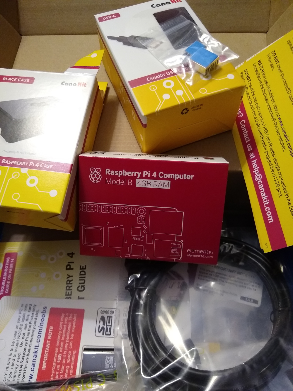
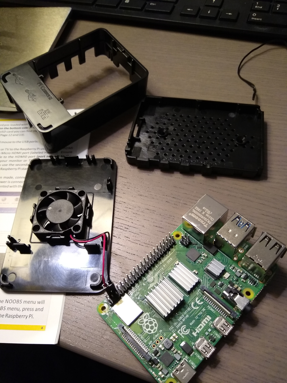
    I decided to re-purpose a pi that was previously running PiHole (and working great). So in order to just have a fresh start, I went ahead and flashed a fresh image of Raspberry Pi OS Lite (64 bit), which I’ve really enjoyed using lately. Since I’m not using some of the more traditional desktop doodads (browsers, music players, keyboard/monitor setups, etc) I don’t need all the extra packages, drivers, and software required to make a full-on desktop OS. So the lite version has been perfect for just getting up and running as quickly (and lightly) as possible allowing me to only install the packages that I’ll actually be using.

    Step 1: Pi Setup

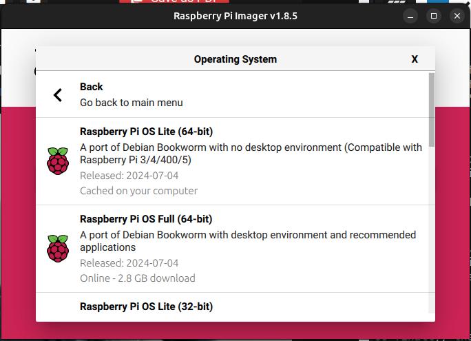
    If you’re using the Raspberry Pi Imager (screenshot above) then you’ll also receive the options to set your own username, non-default password, enable SSH, setup wifi credentials (if needed, but not recommended for this application) so all you need to do is flash the SD card, plug in your Pi, and it will be immediately accessible the moment it boots up and comes online. Pretty sweet!

    Step 1.5: Port Forwarding

    Make sure your pi has a static IP address (the pivpn script in the next step should help ensure this) and that your router is forwarding to your Pi. If you don’t do this step, your Pi won’t be accessible from outside the network and that will basically defeat the entire purpose of this particular setup.

    Step 2: PiVPN

    Before we go any farther, because this is a brand new Pi OS install, it’s always a good idea to run:

    sudo apt update && sudo apt upgrade

    For this setup, we’re gonna be using PiVPN. It’s a really awesome Bash script that will get you all set up in a super-easy, relatively painless series of prompts. Typically, it’s good practice not to pipe random scripts directly into bash (especially if you don’t know what they are and/or don’t know what they do), but because this is a trusted source, we’re literally following the first installation method, which does just that.

    curl -L https://install.pivpn.io | bash

    This will download the latest pivpn release and run the script right on your pi.

    Step 3: Add User

    Once pivpn is up and running on your pi, add a user with pivpn add and that will prompt you to enter in a user/client/device name as well as a (good, strong) password. Once you’ve done that, a new user will be generated and a new .ovpn file will be generated in your home directory. Almost there!

    Once your .ovpn file has been generated, you’ll need to transfer that file to your client (the phone, laptop or other device you’ll be using to remotely connect to your Pi VPN with). With the file transferred, you’ll need to install the OpenVPN client. The client can be found at https://openvpn.net/client/

    Step 4: Connect

    Now you’re ready to connect. On your client device outside your home network, open the OpenVPN client and import the .ovpn file you brought over earlier. This is your connection profile. It contains all the data you need to securely connect to your VPN. It’s very important that you protect this file. If anyone else were to get this file, they too could connect to your VPN and potentially do some serious damage.

    After the file is imported, flip the switch to connect!

    matt

    September 30, 2024
    Raspberry Pi
  • Can We Talk About TMUX

    Can We Talk About TMUX

    What the heck is tmux? I gotta be honest, I didn’t really know or care what tmux was or what it could do until I came up against a problem I didn’t have a solution for. If you’ve been reading along, last week I dusted off my unused Raspberry Pi and hooked it up with an LCD display. Quite a fun project, and I’m definitely not done with it, but, it wasn’t too long after the LED display setup that I ran into a problem.

    The Problem

    You see, just to get started and learn my way around the LCD display, I ran a few scripts just to see if I could successfully display anything on the screen. It worked! As I got closer to my original plan for the Pi project, I wanted to be able to SSH into the Pi, write and execute a long-running script (long-running as in… basically forever) and then EXIT my SSH session and have the script still running. Yeah, as you can imagine, after exiting my SSH session, as soon as I was disconnected, my script would stop running as well. How can I solve this?

    Enter TMUX

    After a bit of searching, it would seem there are a handful of different solutions to this problem nohup, screen and of course tmux. I opted for tmux because I’d heard of it before but never really explored it, and lots of people online really seemed to use it with great satisfaction.

    So what does it do?

    tmux is a terminal multiplexer. Basically, it allows you to place a terminal inside your terminal and a terminal inside that terminal and so on. It’s extremely capable and very powerful, and for my particular use case, I’m barely scratching the surface. But the key feature I needed was tmux‘s ability to disconnect from and resume terminal sessions.

    Setup

    In order to use tmux, you’re gonna need it installed. Great news, it only needs to be installed on your server or the device you’re SSH-ing into. To install it, on Ubuntu/Debian, it’s as easy as sudo apt install tmux. If you’re using a different system, there’s tons of installation methods, and the whole project is on GitHub, so feel free to check it out

    Basics

    Once it’s installed, you can simply run it with tmux. It may not look like much happened, but once you see a little green bar appear at the bottom of your screen, that’s it. You’re IN. It’s just like a regular terminal session, you can do whatever you want (like execute long running scripts, ping google forever, count to a million, whatever). Once your terminal is going, you can detach from that session by hitting the default prefix hotkey CTRL+B (Kinda the Vim-equivalent of ESC, it won’t look like anything happened, but it puts you in “command mode” where tmux is essentially awaiting instructions).

    After you’ve hit CTRL+B, you can detach from the active session with d. That’s it. Done. Now that you’re detached from your tmux session, you can exit the shell (disconnect from your SSH session) and that’s it. You’re free. Go for a walk, drive somewhere, go eat lunch, take a break, whatever.

    Reconnecting

    Then, some time later, let’s say you want to reconnect to that tmux session you started a while ago. Just SSH into that machine running your process (it can even been from a different device, location, or IP!) and you can reattach yourself to the last (most recently run) tmux session with tmux a which is short for tmux attach.

    And boom. That’s it. You’ve reconnected to the terminal session you started some time earlier, you can kill the process, make updates, do whatever you need to do.

    matt

    September 23, 2024
    Linux, Raspberry Pi, Ubuntu
  • Connecting a 20×4 LCD to a Raspberry Pi

    Connecting a 20×4 LCD to a Raspberry Pi

    I’ve had an unused Raspberry Pi laying around the office for quite too long! It’s high time I did something about it. I’ve had several ideas over the last several months as to what to do with it exactly, but they were all similar ideas.

    I wanted to run some sort of automated task on a schedule (cron job) so I wouldn’t have to remember to send those monthly emails or other tasks that are pretty simple, but I always forget to to do them.

    Regardless of what I was doing, I needed a way to keep an eye on the ongoing task, but I also didn’t want to dedicate an entire computer monitor just for the sake of keeping tabs on a monthly task. So instead of doing a full monitor, I thought it would be a good idea to do a smaller LCD screen instead.

    Come to find out, there are tons of articles online showing how to set them up and the LCD screens themselves are relatively cheap and readily available. So I figured I’d give it a shot!

    Getting started

    Before I just pulled up a raspberry pi shop and started throwing a ton of stuff in my cart, I needed to do a bit of research just to understand what I was getting myself into. Obviously, I was going to need that Raspberry Pi (reviving the model 3b+ and putting it back into service), but I wasn’t sure exactly what was needed to get the LCD connected to the pi via the GPIO pins.

    • Raspberry Pi (model 3b+, but pretty much any model should be fine)
    • 20×4 LCD display
    • connector pins (female to female)
    • LCD i2c interface (sometimes called a “backpack” module)

    The i2c interface was the part I didn’t know much about, but apparently it facilitates the protocol through which the Pi communicates with the LCD, it also steps down the voltage coming off the board so you don’t fry your display.

    I ended up getting a model that included the i2c interface, which was really handy! Neatly soldiered to the back of the display, it was very much plug-n-play… so long as you plug the correct pins together.

    I2C module pinout

    On the back of the display module, as you can see, there’s quite a bit of pre-done soldering up at the top of the i2c module! So if you can find one that has that already done for you, I would absolutely recommend going for that one. The only connections I had to match up were GND (Ground), VCC (fairly certain is 3V power, but will need to double check), SDA (some kind of data signal?), and SCL (probably the other data signal, I’m guessing on and off?). Regardless, there’s plenty of GPIO pin breakout images online, just have a look and connect each wire to the appropriate pin.

    Once everything was connected, I booted up a fresh copy of pi OS (like I said, it’s been a while) but instead of doing the FULL OS, I opted for the Pi OS ‘Lite’, which I really like. Because I knew I wasn’t going to be connecting a mouse, keyboard, or monitor directly to this particular Pi, I was able to define my username, password, and internet connection method at the time I was burning the OS, so by the time I boot up, a few seconds later it’s ready to connect via SSH.

    matt

    September 15, 2024
    Raspberry Pi
  • Hosting a React App on Raspberry Pi

    This article assumes you’ve already got a Raspberry Pi set up and running the latest Raspberry Pi OS, and you’ll be hosting a React app locally (meaning it’s only accessible on your local network).

    First you’ll want to enable SSH. There’s some fancy ways to do this in the terminal, but the easiest is to just enable it in the preferences.

    Once you’ve got SSH enabled, there’s one little security doodad you’ll need to fix. You’ll want to open your Pi’s terminal and head over to your config file and edit it with nano: sudo nano /etc/ssh/sshd_config. You potentially won’t need to run this command with sudo, but when you do… you’ll most certainly feel more powerful.

    Once you’re inside, you’ll want to be on the lookout for a line that reads:
    #PermitRootLogin prohibit-password
    Once you find that line, you’ll want to edit it so it reads like so:
    #PermitRootLogin no
    That’s it! You can close out of nano and save your changes.

    Next, you’ll want to confirm which IP address your Pi is using on your local network. Do find this, just type hostname -I.

    UPDATE: Alternatively, an even simpler way to output your PI is literally just ip address. I’m never gonna remember that.

    At this point, you’re pretty much home-free. Hop onto a different computer on your local network and open a terminal. I’m assuming you’ll be ssh-ing from another Mac or Linux machine. Go ahead and SSH into your pi with ssh [username]@[IPaddress] at which point, you’ll be prompted for the password on the Pi to log in. Enter the password and you’ll hit the /home directory of the Pi!

    Now, you can just build out your React app like you would normally, in my case I just installed Node, ran npx create-react-app /some-project and off it went! Once your React app is set up, you can access it from any device on your network by going to the IP address of your Pi (the one that appeared when you ran hostname -I), then a colon with the port number, just like you would on localhost.

    Happy hacking!

    matt

    May 18, 2022
    Linux, Raspberry Pi
  • Arcade Side Quest: Swapping Hardware

    The Problem

    It wasn’t too long ago I uploaded a post on how I built out the Raspberry Pi 4 for the Light Quest arcade project. It was all promising at first, until I did my first test. I figured, before I go down the long, long road of fully developing an entire game from scratch, going through countless revisions (hopefully not countless) and finally getting to the point where I’m ready to deliver the game to run it on the Raspberry Pi, only to find out the game wasn’t compatible with the Pi hardware… It’d be best to just run a simple test first with a game I already had lying around. Yes, I got the controls working for the game, but that was only on my laptop. I wasn’t satisfied until I had a game that I’d written fully functional and running smoothly on the Pi.

    Good news: I ran this check early. Bad news: The test unearthed some unfortunate results. Something that I didn’t completely realize until after the Pi was ordered and assembled and set up with a fresh copy of Raspian, was the fact that Pi’s run ARM CPU architecture. This is great except when you need X86 architecture. The executible Linux binary I had exported for Pi was only compatible and compiled for x86 architecture. When I executed on Pi, it just threw an error and that was that. There was no running the game unless I could export for ARM. After many-a internet searches, almost zero game engines support ARM architecture. I say almost because there were a few examples of crazy experimental setups running Unreal or Unity on ARM boards, but it wasn’t exactly straighforward. Keyword: “experimental”.

    So finally, I came to terms with the fact that it would just be easier to swap hardware in favor of an X86 CPU board instead of forcing the Pi to do what I needed it to do. So after a quick call to IT, they just happen to have a few chromeboxes lying around that were being replaced. Score! I was able to snag one of the boxes for the arcade project. The new gameplan was to wipe the chromebox, install GalliumOS, and test the linux executable on that box. But first, the GalliumOS install. Luckily I have some previous experience with GalliumOS and have installed it on 2 laptops before.

    The first step is finding the four corner screws that keep the main case assembly together. They can easily be located by popping off the rubber feet at the bottom of the chromebox with a small flathead screwdriver or a knife. With those screws exposed, you can pull them out with a Phillips head screwdriver.

    With the four corner screws removed, the top of the case can easily slide off. With the chromebox top removed, you can get a good look at the internal components. Upon careful inspection and a little bit of help from Mr. Chromebox, I was able to find the write-protect screw. Yes, there is a physical screw that protects custom firmware from being written without removing this screw. I guess Google doesn’t want anyone to accidentally boot a different operating system.

    Once the write protect screw is removed, I was able to close everything back up and boot into GalliumOS without having to hit CTRL+L every single time to make sure that it boots into legacy mode. And with a few settings tweaked, I now have a chromebox that automatically logs in as admin at boot and launches the Linux binary executable that I was testing on the Raspberry Pi 4 that was failing previously. Problem solved.

    matt

    May 11, 2021
    Light Quest, Linux, Raspberry Pi
  • Arcade Parts Arrived

    Today was a good day! The parts arrived for the arcade cabinet build. I got a Raspberry Pi 4 kit with case, pre-programmed SD card, HDMI to micro cable, power, and a DIY arcade kit that included several different colored buttons, joysticks and parts. Woo!

    Step 1: Take everything out of the box(s)

    There was actually quite a large number of parts that all arrived in something the size of a shoe box. The Pi and all of its components and then the arcade hardware and all of their components. To be fair, the buttons and joysticks had a great feel to them. They were nice and weighty, and the joysticks had a very satisfying click when you moved it any direction.

    Step 2: Apply Cooling Fins to Pi

    If you’ve been following my posts for some time, you’ll have probably run across a few posts that have covered some projects that were completed using the Raspberry Pi 3b+. This arcade cabinet will be completed with the model 4, so I’m really excited to check out some of the differences between the two models. One of the first differences I noticed right off the bat was the USB-C port for power and dual micro HDMI ports for multi-monitor support. Nice! First up, installing the included cooling fins to keep the Pi cool when it’s working hard.

    Seemed kinda simple at face value, especially since they didn’t require any thermal paste or anything. It was just a pre-applied adhesive that you just peel the protective blue plastic off and stick it. Easier said than done. These parts were small… especially the smallest one! To do it with my big fat fingers, well… I could already see that wasn’t going to work. Also, on the Model 3, the fins, I’m pretty sure, were all square, and there were only two of them. On the Model 4, there’s an extra cooling fin that’s super small, and new rectangle shaped one. Since the rectangle shaped fin could only be applied one way, I decided to apply the two remaining square fins so that the fins all faced the same direction. Not required, and nobody will see this because the case is actually solid black, but I try my best to be neat and tidy when it comes to putting computers together. Anyway, time to break out the needle nose pliers!

    Step 3: Install fan

    This one was actually pretty nice! My Model 3 didn’t come with a fan, I didn’t realize I needed a fan, but awesome! My only complaint (and it’s really not that big of a deal) was that there was no arrow on the fan that indicated air direction. So I just followed the instructions on the quick start guide to plug the wires into the GPIO pins, gave it power, and checked the air flow direction. For those of you curious, the air flows in the direction of the CanaKit logo. So instead of pulling air into the Pi case and not really having anywhere for it to go, I wanted the fan to pull hot air out of the case to promote cooling. I know it’s not like a full tower build where you’d actually have to consider airflow and pressure and heat and all that, but that was my thought process. It is a little computer, after all.[ ]

    Once I knew the air direction, I clicked the fan into the top lid of the Pi case so the air would blow out of the Pi shaped vent hole at the top. I made sure the fan was still plugged in the correct GPIO pins (since I plugged them in once for testing, I needed to unplug them in order to attach the fan to the case lid) and sealed everything inside.

    Step 4: Done!

    Obviously, this was just covering the basic Pi assembly, there’s definitely a lot more to come. We haven’t even picked up the blank arcade cabinet yet! That happens next week. Get excited! Here we go!

    matt

    April 16, 2021
    Light Quest, Raspberry Pi
  • I Created an RFID Check-In Prototype With a Raspberry Pi

    All the technical details (and more awesome pi projects!): https://pimylifeup.com/raspberry-pi-rfid-attendance-system/

    RFID Check-In on a Raspberry Pi

    Hey guys! What’s going on my name is Matt and today I’m not doing a museum update and I’m not doing a 3d house model those
    are two other projects that are crazy and I’ve been doing other stuff and so…


    This video is for one of the projects that fell through the cracks if I don’t
    make a video about it no one will ever know that I did it so let’s do it!

    So a while back somebody came to me and asked me to do a project for a small like a kids ministry thing at church and they needed a way to get kids checked in and have like an account for each kid on this app, right… And so they needed to play games on the app and they you know keep they earn points and all this kind of stuff to kind of keep track of all of everybody’s stuff. So the first phase of creating this app I thought will they have these bracelets that have RFID tags on them and so if you could use that to track the kids and keep track of how many points they have each. That might be a good starting point so I created an RFID chicken system as a prototype for the app that never happened so here you go:

    Alright guys, so the very first thing that I grabbed was a Raspberry Pi and an RFID reader writer module so I can read the the actual tags themselves. So once I got those things together, I started to work on the wiring of the RFID module to the Raspberry Pi itself. And so that was put together with a breadboard and if you guys want some more information on exactly how that’s all rigged up there’s a link and in the description. And so once I had all the wires run from the RFID module to the Raspberry Pi it was time to boot up. And so once I booted up I was able to create two Python files and save them in a special RFID directory inside of the Raspberry Pi.

    So the first one is called read and it does just what you might expect it to it will read the identification number on the RFID tag and so every single tag that is created has an ID number and so the read function inside of the script will print out that number and any other information that’s written to that particular tag if nothing else is written it will just print the ID so
    that is the script for reading the tags and then there’s a second script that is
    write PI and it does the same exact thing except for your writing additional
    information to the tag so in order for the scripts to function you need to
    execute them so first off I’ll just execute the read function so once you
    execute it it’s going to enter a like a listening mode so when it detects an
    RFID tag that has been tapped to the sensor it will say okay I see the tag
    and here’s the ID number any other additional information written to that
    tag and in order to write to the tag you just execute the right program and then it’ll ask you to enter a little bit of text or whatever information that you want to associate with that particular tag so for my example I just put a string of text that says it is written and then once I wrote that to the tag I
    was able to read that information back and output that to the terminal.

    Alright guys thanks for hanging out if you want to know more about this RFID reader writer I have some more information and technical details and wiring diagrams and all that good stuff in the link below and hope you guys enjoyed this one we’re gonna be neck we’re gonna be back next time probably on home design 3d animation need things but I’d like to
    get back on the museum train that’d be great so we’ll see how it goes
    and I’ll see you guys next week peace out!

    matt

    May 12, 2020
    General Computing, Linux, Raspberry Pi
    attendance, check-in, DIY, python, raspberry pi, rfid
  • How To Set Up a Raspberry Pi 3 B+

    Prerequisites

    For this tutorial, I’m going to assume that you’ve got enough hardware to get started. And if you got your Raspberry Pi as part of a kit, then you should be good to go. You should have the following:

    • Raspberry Pi board
    • Raspberry Pi power supply (micro USB Output 5V DC 2.5A Regulated, Input 100V to 240V AC)
    • Raspberry Pi case (not technically required, but I definitely want to protect my pi!)
    • Micro SD card (at least a class 10)
    • HDMI cable (full size, male to male)
    • Monitor or television capable of displaying output from a full HDMI port
    • USB-A mouse
    • USB-A keyboard
    • A computer
    • A micro SD card reader

    Download your OS

    You can run tons of different operating systems on your Raspberry Pi, but for this demo, we’ll go with the OS officially supported by the Raspberry Pi Foundation called Raspian (based on Linux Debian). You can download the operating system here. Once you have the operating system downloaded, you’ll want to head over and download the latest version of Etcher.

    Etcher is a great, simple, open source software used to create bootable media. Use Etcher to select your downloaded copy of Raspian. Next, select your micro SD card as the volume to burn to. Then click go! It will take several minutes to write the OS to the micro SD and then validate the burn. Once it’s complete, eject your SD card and you’re ready for the next step.

    Boot your new Raspberry Pi

    With your freshly burned SD card inserted into your Pi, connect the keyboard, mouse, and monitor, and plug power into your pi. There isn’t a power button on the pi, so as soon as power starts running through the board, it will automatically start the boot process. You should be greeted with a simple setup wizard to help you configure some settings that will be applied every time you boot your pi in the future.

    That’s it! Enjoy your new Pi!

    matt

    April 30, 2019
    Lifestyle, Linux, Raspberry Pi
    debian, DIY, linux, pi, raspberry pi, raspberry pi 3, raspberry pi 3 b+, raspian, setup

Prove all things; hold fast that which is good. 1 Thess 5:21